
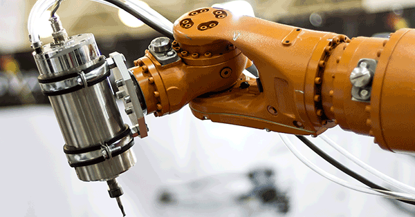
Automated Liquid Handling systems are the preferred method when accurate dispensing of liquids is required. Two common architectures for dispensing are contact and jet dispensing. The use of a mechanical syringe enables contact dispensing to be used, which can be more accurate than jet dispensing even though the latter is a faster process. For line dispensing, which is used for things like applying adhesives, contact dispensing is the primary method since typically the line must be contiguous. Also, a syringe has added functionality since it can aspirate as well as dispense, something not available with jet dispensing.
Controlling the amount of liquid deposited is critical in applications where there is “Keep-Out-Zones” present along with other requirements which affect the desired geometry of the deposited liquid. Deposit geometries which are equal to or smaller than the size of the syringe tip nozzle cross-section present additional control challenges. At this scale, the liquid meniscus at the tip of the nozzle becomes significant.
The automation in a liquid handling system allows the syringe plunger’s position and the nozzle height to be changed dynamically during operation while maintaining extremely accurate position control. A critical function of the system is to control the meniscus height when contact with the work surface is made or when the nozzle is retracted. If the nozzle height deviates too far from optimal, the deposited liquid geometry can become unacceptable.
The motion of the nozzle and plunger after the liquid has contacted the work surface is also critical to controlling the deposit geometry. If the application is dispensing a “dot”, most likely the nozzle will begin to move up while the plunger continues to move down. However, there could be applications where one of those is at rest for some time period. If the application is dispensing a “line”, the same control parameters (nozzle height and plunger position) are still relevant but now the translation of the nozzle along the work surface becomes critical.
Typically, small electric motors will be selected to generate the motions described above. The machine designer is left to choose between selecting open loop architectures (step motors) or closed loop architectures (Brushed or Brushless motors). The step motor will appear desirable since smaller step motors can generate the same torque as a larger Brushless motor and step motors do not necessarily require position feedback. This paper will demonstrate dispensing applications where the required motion accuracy can only be achieved with a closed loop control architecture (position feedback).
Introduction
Focus will be given to the motor which operates the syringe, however, the motors which control the nozzle height and translation are certainly critical as well. The size of the selected syringe motor must be large enough to generate the required torque. However, the size will be limited by geometric constraints based on the location of the motor in the machine. Weight limitations also exist since it will likely be in motion along with the nozzle. In order to maximize machine functionality, it’s typical to create a syringe cluster in the liquid handler. This will minimize the amount of horizontal space available for the motor but does allow for significant vertical space. Since the motor can be mounted vertically, the designer can choose a small diameter motor and add a gearbox to increase torque. A planetary gearbox will effectively add length and torque to the motor without adding to the diameter. A leadscrew is used to convert the rotation of the output gear to vertical translation of the syringe. The effects of the gear and lead screw will be represented by a single translation ratio and efficiency value.

A syringe was selected which can aspirate and dispense a 100uL volume liquid. A planetary gear and lead screw assembly was selected which provides a kinematic ratio of 0.04 mm/rad and 80% efficiency.
The mechanical loading on the motor is a result of the friction associated with the contact at the plunger/vessel interface surface, frictional loss in the gear assembly, motor rotor inertia and gear assembly inertia. Both Coulomb and viscous friction are present there. A 12mm diameter step motor was selected which can produce up to 3 mNm of torque.
|
Motor Diameter |
12mm |
|
Step Size |
1.8o (50 pole pairs) |
|
Motor Torque |
3mNm |
|
Gear Assembly Kinematic Ratio |
0.04 mm/rad |
|
Gear Assembly Efficiency |
80% |
|
Volumetric Displacement |
8.3uL/mm |
The resulting system architecture is open loop since there is no position feedback present. The cost of an incremental position encoder has been avoided, however, the position accuracy is not being explicitly controlled and is at the mercy of the step motor’s response.
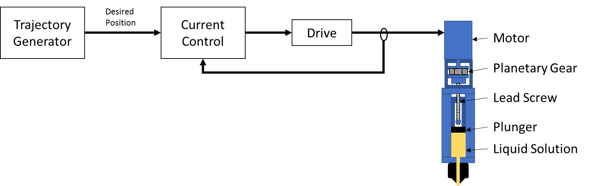
Figure 1: Open Loop Architecture
At this point, a significant architectural question arises as to whether a position loop is required to achieve the desired deposit geometry. Position loop closure requires position feedback and therefore a position encoder (500 cpr) has been added to permit a closed loop architecture. Closing a position loop on a servo motor (Brushed and BLDC) is more common, however it is still possible on a step motor. In order to be consistent, the same step motor will be used in both architectures. Note: “Open/Closed Loop” is referring to position control. A closed current loop exists in both architectures.
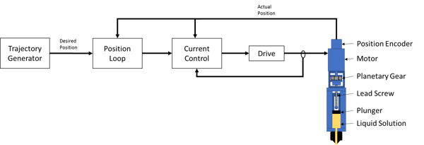
Figure 2: Closed Loop Architecture
Method
Application Dependencies
The requirements for deposit geometry will affect the acceptable positional tolerance of the plunger during the dispensing process. Those requirements will vary based on the application. For example, when dispensing a “dot” geometry the desired motion of the plunger is simple and can include a pause which allows the motor’s positional response to go to a steady state. During the pause, assuming it's long enough, the only significant system-level force acting on the motor is Coulomb friction at the plunger/vessel interfaces and bearings.
In contrast, when dispensing a “line” geometry the desired motion of the plunger will not come to rest. To further complicate the process, depending on the adhesive properties of the surface and the surface tension of the liquid solution, a “dog bone effect” can occur at the ends of the line. This can result in a process failure if the deposit breaches the Keep-Out-Zone (KOZ). (Breach area is shown in red).
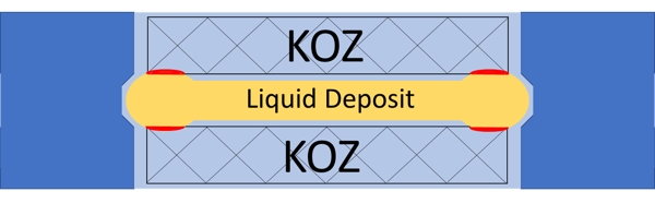
Figure 3: Dog Bone Effect
Solutions for avoiding the dog bone effect have been investigated which lead to the realization that advanced techniques are required. “A dynamic dispense control i.e., a dispense rate correlated to the head motion can mitigate the issue.”1 The performance difference of the two architectures can be examined in the application context of a more complex line dispensing process that utilizes the “suck back” process. The application involves an absorbent surface and a liquid solution with low surface tension. A “suck back” process is required to avoid the dog bone effect which means the plunger will temporarily move upward shortly after the first contact. This will reduce the pressure on top of the liquid column which will counteract the first contact flow surge onto the surface. This is also the point at which the translation of the nozzle in the direction of the line begins.
Architectural Analysis
Figure 4 shows the beginning of the analysis when the syringe starts moving down to initiate the dispensing process (t=0). The suck back process begins when the liquid makes first contact with the surface (t=80ms). The syringe then reverses and moves in the aspirate (positive) direction to counteract the first contact flow surge.
The translation of the nozzle in the direction of the line begins. About 50ms later the suck back process ends which corresponds to the nozzle translation reaching full speed.
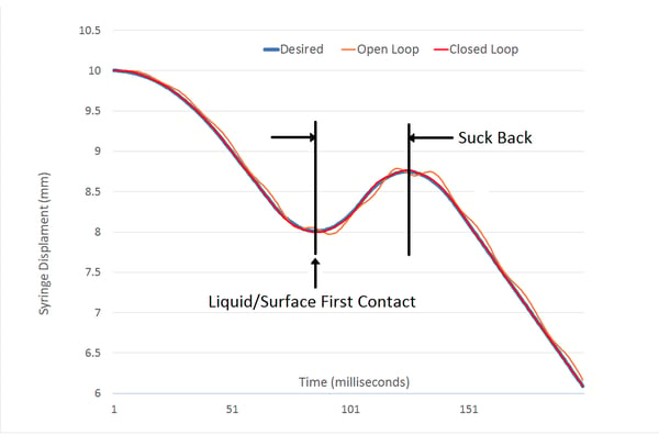
Figure 4: Architectural Comparison
Figure 4 also shows the positional response of the two candidate architectures: Open Loop (Orange) and Closed Loop (Red). The effects can be seen more easily in the position error data in Figure 5.
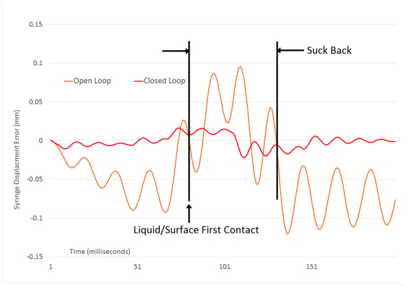
Figure 5: Position Error Comparison
The closed loop architecture minimizes the position error as compared to the open loop case. This is not a surprising result since there is a control loop dedicated to minimizing the position error which does not exist in the open loop case. Also, as seen in Figure 2, the current loop will use the position feedback signal in addition to the winding current measurements. This provides the current loop with knowledge of the instantaneous motor/stator alignment which is used to generate an applied electrical angle to optimize torque.
The position error of the open loop response during the suck back process is many times larger than the closed loop error. The error is positive which means there will be significant lag and the pressure at the top of the liquid column will not decrease enough to properly affect the flow. The resulting overflow can cause a dog bone large enough to breach the KOZ.
There are changes that can be made to improve the open loop error. One option is slowing down the move by using smaller acceleration and velocity values. However, the process throughput of the system will suffer, as the time required to dispense the line will increase. Another possible system change is to decrease the reduction ratio of the gear/lead screw assembly. This has several drawbacks one being the motor will now need to spin faster and it may be beyond its rated speed. Another is that the efficiency will decrease causing an increase in thermal power loss.
Conclusion
The system designer of a liquid handling machine should always consider both architectures. The open loop architecture does not include the cost of position feedback and therefore should be used if the response is acceptable. However, there are some liquid handling applications where the open loop response will result in process failure, in which case the use of a closed loop architecture could reduce the position error by 5x or more. The focus was given to the syringe motion since that has direct control of the liquid flow. However, the architectural comparison is still relevant to other motion on the machine such as the motors which translate the nozzle along a path.
Article was written by:
Thomas Keller MSc.
Peter Vandermuelen MSc. MBA
Chuck Lewin
Juno Family of ICs
The Juno family of velocity & torque control ICs are perfect for building your own low cost, high performance pump controller. Juno ICs feature advanced velocity control with dual biquads, torque mapping, deadband filters, profiling, FOC (Field Oriented Control), and more. Available for BLDC, DC Brush, and step motors, these compact ICs are an ideal solution for your next liquid pumping design.
Learn more >>
Magellan MC58113
The MC58113 is part of PMD's popular Magellan Motion Control IC family and provides advanced position control for BLDC, DC Brush, and step motors alike. Standard features include s-curve profiling, programmable breakpoints, two axes of encoder input, FOC (Field Oriented Control), intelligent performance trace, and more. Whether used for peristaltic pump control, syringe pumps, or gantry control, the MC58113 family of ICs are the ideal solution for your next liquid handling and positioning application challenge.
Learn more >>
ION Digital Drives
ION Digital Drives combine a single axis Magellan IC and an ultra-efficient digital amplifier into a compact rugged package. In addition to advanced servo motor control, IONs provide S-curve point to point moves, i2T power management, downloadable user code, and a range of safety functions including over current, over voltage, and over temperature detect. IONs are easy to use plug and play devices that will get your next laboratory equipment or patient treatment design up and running in a snap.
Learn more >>
You may also be interested in:
- Precision Fluid Handling - A Case Study
- Closed Loop Steppers Drive New Motion Control Applications
- Step Motor Noise and How to Fix It
- Improving Liquid Handling Robot Throughput by means of Direct Path Planning and Obstacle Avoidance Programming